Quickstart
Already set up your hardware? Skip to software setup.
There is also a printed assembly guide in English and German that is bundled with Ten64 retail purchases from June 2024 onwards. The PDF version can be downloaded here.
Before you plug in the power
Opening the enclosure
For Ten64 desktop enclosure users, the rear panel is fastened with 4 x M2.5 hex/socket cap screws. A hex key to open the enclosure comes in the accessories pack.
Use the hex key to unscrew the rear panel, after which you can pull the top cover plate out for easy access.
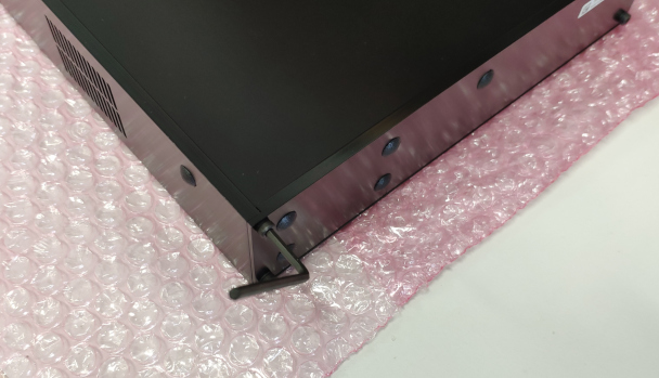
The rear panel keeps the motherboard tray in place. We recommend having the rear panel installed at all times, including when the lid is removed.
Inserting the SODIMM
See article: DDR
The procedure to insert the SODIMM is:
- Lean the SODIMM at a 45 degree angle, towards the SoC
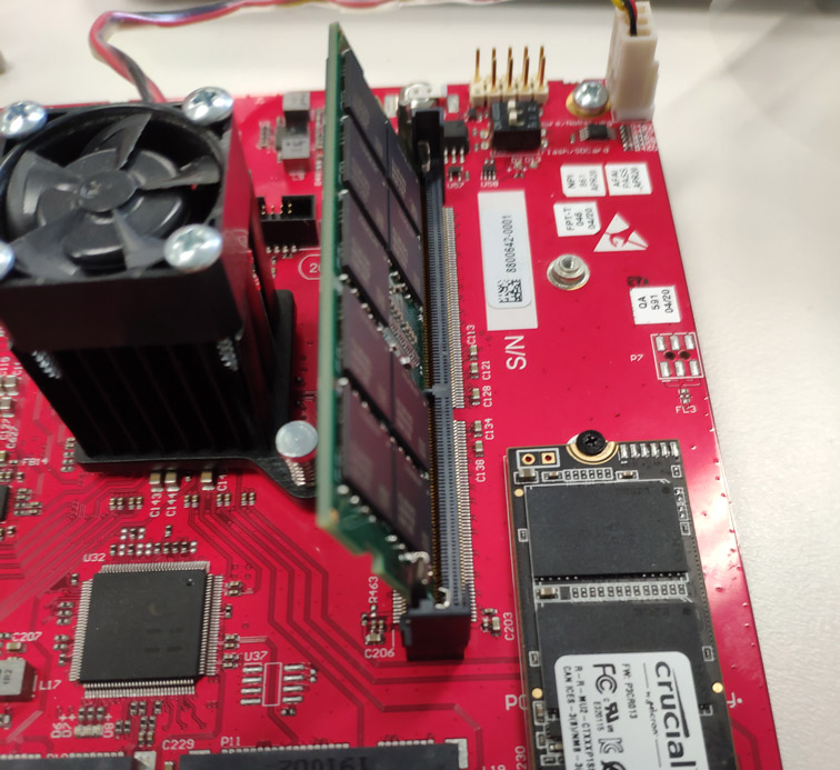
- Push the SODIMM down into the slot
- Push the SODIMM backwards (away from the SoC) until it is captured by the slot latches and is fully upright.
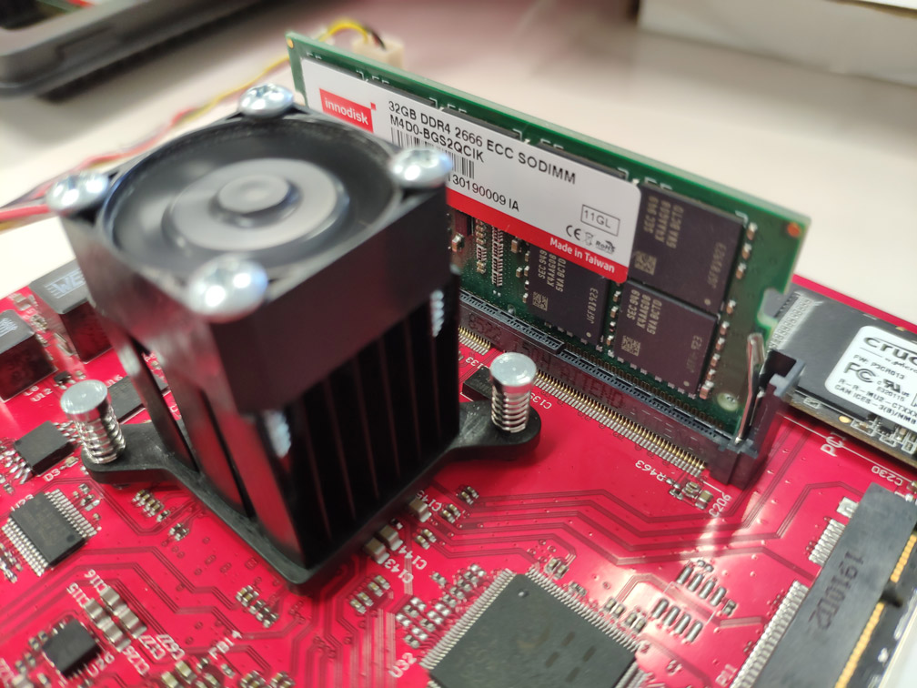
If you can see the gold contacts on the SODIMM then it has not been fully pushed down into the slot.
To release the SODIMM, push both the latches away from the card edge.
Note
Some brands (such as Kingston) have modules that are thicker than normal (but still within spec). You may need to apply more force than expected to insert them.
ATX front panel pinout (for ATX/ITX users)
The ATX front panel pins follow the standard layout - on recent ATX/ITX cases the front panel connector will plug straight in:
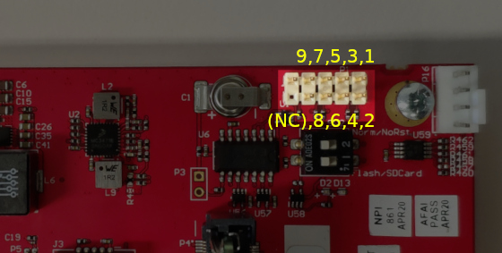
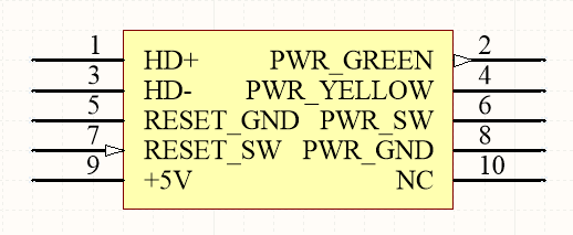
Note: Pin 10 (NC) is a 'key' pin - it is not on the board or connector.
See article: Power Connector
For desktop/12V power supplies, we recommend plugging in the barrel connector on the Ten64 end first, and then inserting the AC cable into the power point.
This provides a smoother start-up (and vice-versa for power off), as the barrel connector has a mechanical 'bounce' effect during insertion.
DIP Switch and board LED
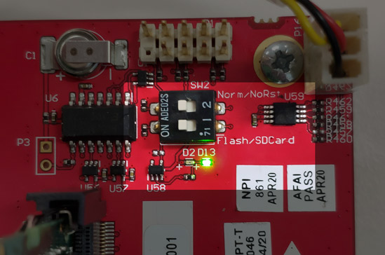
DIP switch 1 (nearest LED) controls whether the board loads the boot firmware from the onboard QSPI flash or via SD card - the latter is useful when you need to "unbrick" from a bad TF/U-Boot version.
DIP switch 2 inhibits the RESET_REQ(uest) line from the SoC to the board controller, typically this is only used when doing low level board firmware development, e.g testing different RCW settings.
The LEDs below the DIP switch denotes the current board status - green for when the board is operational, red for failure or sleep/power off.
Reset button
Both the rear reset button (top button on I/O panel) and ATX reset need to be held down for at least five seconds before a reset is triggered. This is to prevent accidental resets.
The reset behaviour (e.g ignoring reset or increasing the required button duration) can be configured with the Ten64 microcontroller utility.
Serial console
Note
Serial console not responding to input? Ensure flow control is turned off in your terminal program.
A FTDI bridge on board provides a USB serial console on the USB-C port.
Settings are the typical 115200,8,N,1 with no flow control.
Tip: Every FTDI chip has a unique ID, under Linux you can add udev rules to provide a consistent name for each board you connect to.
The serial console UART is also available on the Control Header for raw, 3.3V level access.
Please note: the serial console may disconnect momentarily when the Ten64 when the 12V DC connector is inserted. This effect can generally be avoided by connecting/disconnecting power at the AC end rather than the DC end (see above).
SD/SIM tray
Note
Always remove power from the board when removing and inserting the SD/SIM tray.
There is protection circuitry on the board to ensure 'hotswaps' do not damage it, but to prevent any unintended side effects please power down first.
Ten64 has a 3-choose-2 SD/SIM tray, like some recent smartphones. You can have:
- 1 SIM, 1 microSD card
- 2 SIMs, 2nd SIM in microSD position
Support for two SIMs / the 2nd SIM position is dependent on the modem being used.
Getting started with software
Recovery environment
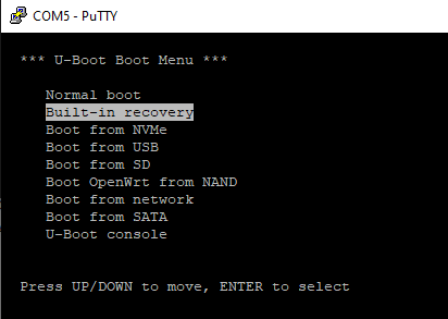
On board the NAND flash is a "recovery" environment that provides tools necessary to partition disk drives, download disk images or chroot into an install. This can be accessed through the "Built-in recovery" menu option at boot or by typing run bootcmd_recovery in the U-Boot shell.
See the recovery firmware page for more details.
Note
Not seeing a command prompt after booting recovery? Try hitting the 'Enter' key a couple of times.
Network and Kernel setup activity may cause the Please press Enter to activate this console prompt to scroll right past you.
Realtime Clock (RTC)
Ten64 uses a supercapacitor-based real time clock for timekeeping. Compared to coin-cell batteries these will only keep time for 48-72 hours when the power is off. As a Ten64 is usually 'always on' this avoids having to replace and dispose of coin-cell batteries.
When you connect to the internet in the recovery firmware (using set-wan) a time sync (using NTP) is performed automatically.
We recommend having the time set before installing any operating systems.
Using the on-board OpenWrt
The on-board NAND flash contains an OpenWrt image which allows you to use your Ten64 as a router right away without having to install a SSD or flash drive.
At the boot menu you can select "Boot OpenWrt from NAND"
To make the on-board OpenWrt NAND, you can modify the boot_targets variable in U-Boot to put openwrt_nand first:
=> print boot_targets
boot_targets=nvme0 mmc0 usb0 openwrt_nand backstop

=> setenv boot_targets 'openwrt_nand nvme0 mmc0 usb0 backstop'

=> print boot_targets
boot_targets=openwrt_nand nvme0 mmc0 usb0 backstop

=> saveenv
Saving Environment to SPI Flash... Erasing SPI flash...Writing to SPI flash...done
Loading a distribution onto a storage device (e.g SSD)
The bare metal appliance store provides a simple way to download a distribution image and write it to your storage device, while also installing any fixups or patches to ensure they run on the Ten64.
After booting into recovery and connecting an Ethernet cable:
set-wan ethX (where X is an Ethernet port connected to the internet)
appstore-list
baremetal-deploy debian-testing /dev/nvme0n1
Using distribution installer ISOs
It is also possible to use a standard distribution installer (e.g ISO image), by writing the ISO to a USB flash drive and booting from it.
As most distributions require tweaks or updated kernel versions to work, we recommend using the appliance store for now.