Control/Hacker header
Note
Looking for power,reset and LED connections for normal (ATX) enclosures?
See "ATX front panel pinout" in the quickstart page.
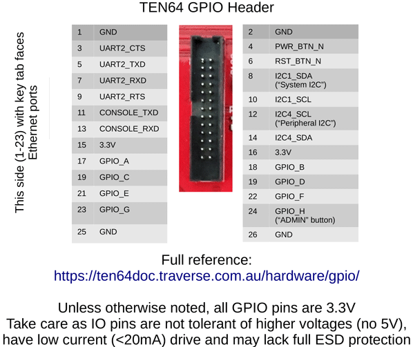
The Ten64 has a 26-pin, 1.27mm pitch control header that includes:
- System console UART (two-wire, 3.3V)
- Four wire UART (UART2, 3.3V)
- System I2C [I2C1] bus
- Peripheral I2C bus [I2C4]
- External power button input
- External reset button input
- Eight, 3.3V GPIOs direct from the SoC, with both GIC and GPIO interrupt capability.
- 3.3V and GND pins
The header is modelled after the 96boards pinout, due to different constraints in media vs networking SoC products it was not possible for us to implement the full connector pinout or to use the 1.8V voltages called for. The connector is physically different from the 96boards one.
The board side of the header is a CNC Tech 3221-26-0100-00, this mates with the 3230-26-0103-00 ribbon cable connector.
With the control header you can control the Ten64 board from another processor, to build IPMI/BMC like functionality.
| Pin | Name | Name | Pin |
|---|---|---|---|
| 1 | GND | GND | 2 |
| 3 | UART2_CTS | PWR_BTN_N | 4 |
| 5 | UART2_TXD | RST_BTN_N | 6 |
| 7 | UART2_RXD | I2C1_SDA | 8 |
| 9 | UART2_RTS | I2C1_SCL | 10 |
| 11 | CONSOLE_TXD | I2C4_SCL | 12 |
| 13 | CONSOLE_RXD | I2C4_SDA | 14 |
| 15 | +3.3V | +3.3V | 16 |
| 17 | GPIO_A / IRQ_03 | GPIO_B / IRQ_04 | 18 |
| 19 | GPIO_C / IRQ_05 | GPIO_D / IRQ_06 | 20 |
| 21 | GPIO_E / IRQ_07 | GPIO_F / IRQ_08 | 22 |
| 23 | GPIO_G / IRQ_09 | GPIO_H / IRQ_10 / Recovery Mode Button | 24 |
| 25 | GND | GND | 26 |
Notes:
- PWR_BTN_N is pulled up to 3V3_ALW, on boards powered from ATX supplies it will always have a pull up. Asserting PWR_BTN_N low causes the board to power off or on.
- RST_BTN_N has a pull up to +3.3V, asserting it low causes a board reset.
-
Using an I2C "isolator" to prevent an external system from holding down the I2C busses is recommended - e.g some SBCs might drive their I2C pins as GPIO until the kernel is booted.
- One possible way to do this would be to use a PCA9306 and it's EN pin to gate access only when needed.
-
GPIO and IRQ pins can function as both normal GPIOs (default), with interrupts via the GPIO controller, or as GIC interrupt pins, direct from the CPUs interrupt controller. Note that GIC interrupts are active high (as they are normally intended for use between SoC IP blocks).
- The UART/CONSOLE TXD and RXD pins are labeled the opposite of the common usage; 'TXD' means transmit from the connected device (received by the SoC), and 'RXD' means transmit to the connected device (sent by the SOC).
- When the onboard USB-C console is active, it will hold the CONSOLE_TXD pin (into the LS1088) high and prevent another device from sending data.