Power Connector
The Ten64 board has an eight-pin, 3.0mm pitch "MiniFit"-style power connector that supports
both DC (e.g from a plugpack) and ATX power supplies (with 5VSB and power on/off) via an adaptor.
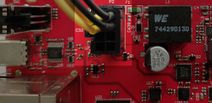
Connector pinout
| (Front of connector) | Net | Net | (Back of connector) |
|---|---|---|---|
| +12V | GND | ||
| (TAB) | +12V | GND | |
| (TAB) | 5VSB | PWR_GOOD | |
| PWR_ON# | GND |
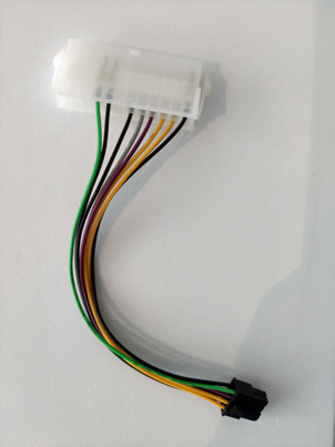
ATX adaptor schematic
An ATX power supply adaptor is available in our 'Mini-ITX' kit (sold separately from the appliance).
Note
Ten64 only draws power from the +12V rail. Older ATX power supplies might shutdown soon after boot, when little or no power is drawn from their +5V or +3V3 rails.
On some datasheets this is indicated as 'Zero minimum load on 3.3 V rail' support or similar.
If 5VSB is present, the onboard microcontroller will go into ATX mode and assert PWR_ON once PWR_GOOD is indicated by the supply. If a power down command is issued by the software, the microcontroller will deassert PWR_ON to effect a shutdown.
| Net | ATX Pin | TEN64 Pin | Wire Color |
|---|---|---|---|
| 12V1_10 | 10 | 5 | 0 |
| 12V1_11 | 11 | 6 | 0 |
| 5VSB | 9 | 7 | 0 |
| PWR_ON | 16 | 8 | 0 |
| PWR_GOOD | 8 | 3 | 0 |
| COM7 | 7 | 1 | 0 |
| COM17 | 17 | 2 | 0 |
| COM24 | 24 | 4 | 0 |
Note: This is not the same as the ATX12VO connector, which is a larger, 4.2mm-pitch connector and uses 12V instead of 5V for standby. Nonetheless, an adaptor may be provided for ATX12VO in the future.